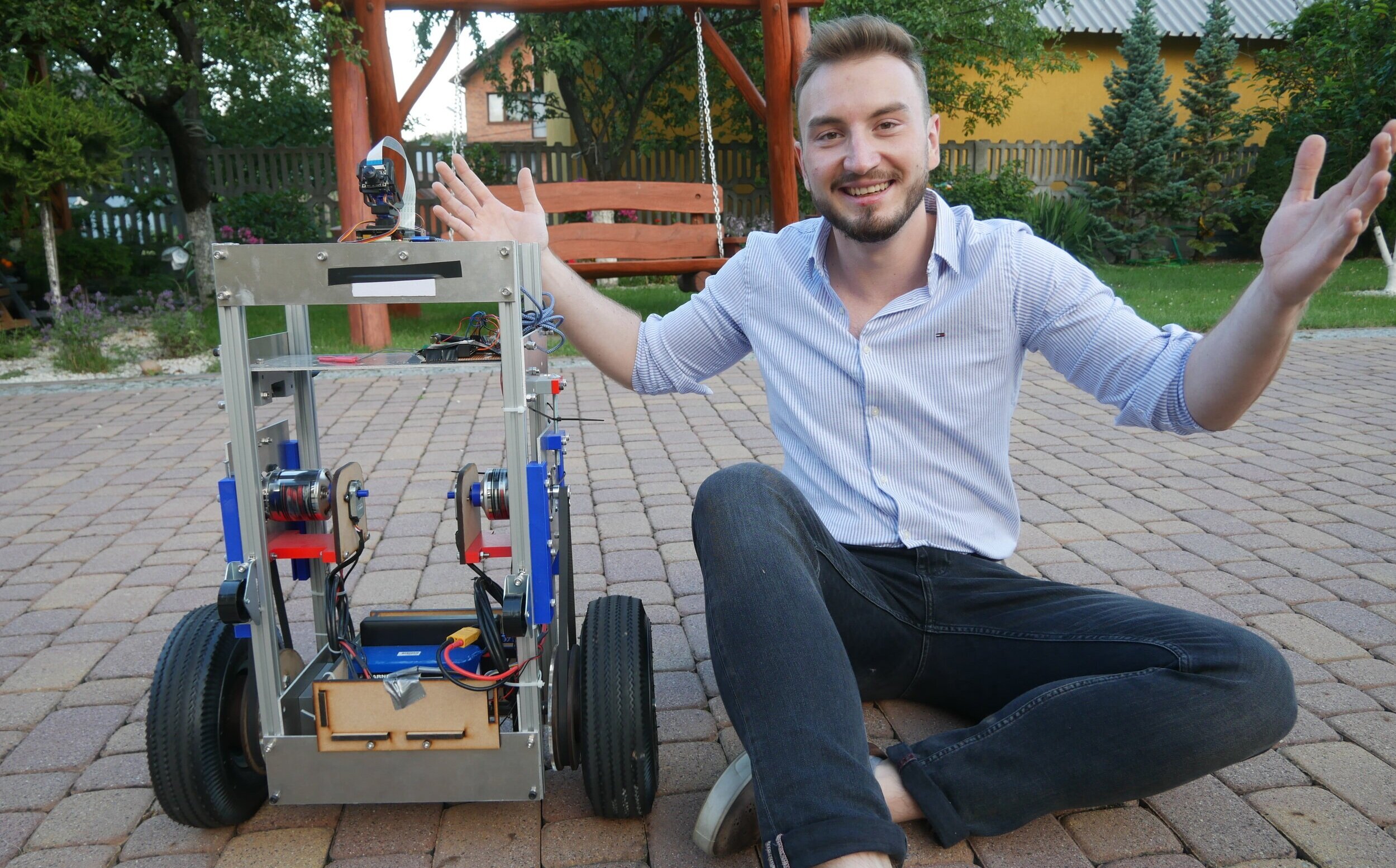
Personal assistant robot
One day I thought “Hey, wouldn’t it be nice to have a robot that would be like your personal assistant? You know, bring me that, brew a cup of coffee, carry my suitcase etc”.
This thought was so captivating I decided to start working on it. The idea was too big to be realised fully and it had to be narrowed down to a minimum viable product. That’s how, after roughly 6 months, Puter - the personal assistant robot, was conceived. Let me take you on a journey through the creative and manufacturing processes!

In the image and likeness of human
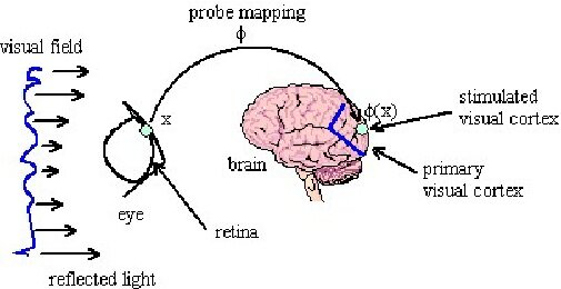
Puter needs to operate effectively in human environments. One of the ways to achieve that is to reflect the fundamentals of humans in its design. Physical appearance is based on a form factor of the human body. The movement of the robot is inspired by the way we walk - constant oscillation between balance and the lack of thereof. The robot is operating as a two-wheeled, self-balancing system. The world is sensed using a camera coupled with the computer vision system, similarly to the eye and visual cortex.

Proportions

Walking mechanics

Vision system
Mechanical design&manufacture
After settling on a design route, the first thing to do was to choose appropriate components and create CAD designs. The robot, with powertrain, drivetrain, frame, and electronics was modeled using Solidworks.
All mechanical components, besides rubbered wheels, were manufactured in the university workshop, using techniques such as 3D printing, laser cutting, and a variety of hand and power tools. Check out the Bill of Materials below
ID |
Name |
Quantity |
Manufacturing process |
Material |
1 |
Rexroth Extrusion |
4 |
Cut to length using saw |
Aluminium |
2 |
Top front/back plate |
2 |
Laser cut |
Aluminium |
3 |
Bottom front/back plate |
2 |
Laser cut |
Aluminium |
4 |
Electronics plate |
1 |
Laser cut |
Aluminium |
5 |
Upper side plate |
2 |
Laser cut |
Aluminium |
6 |
Lower side plate |
2 |
Laser cut |
Aluminium |
7 |
Motor plate |
2 |
Laser Cut |
Aluminium |
8 |
Motor plate rail |
4 |
3D printing |
PLA |
9 |
Pneumatic wheel |
2 |
Purchased |
Rubber |
10 |
16mm shaft |
1 |
Cut to length using saw |
Steel |
11 |
Big timing pulley |
2 |
Laser cut + glue |
MDF |
12 |
Shaft holder |
2 |
3D printing |
PLA |
13 |
Belt tension assembly |
2 |
3D printing |
PLA + steel |
14 |
DC motor - |
2 |
Purchased |
Misc |
15 |
Rotary encoder |
2 |
Purchased |
Misc |
16 |
Encoder plate |
2 |
3D printing |
PLA |
17 |
Enc. plate spacer |
2 |
3D printing |
PLA |
18 |
Small timin pulley |
2 |
Purchased |
Aluminium |
19 |
Secondary DC motor shaft |
2 |
3D printing |
PLA |
20 |
DC battery |
1 |
Purchased |
LiPo |
21 |
Electronic speed controller |
1 |
Purchased |
Misc |
22 |
CPU - Raspberry Pi |
1 |
Purchased |
Misc |
23 |
Microcontroller Teensy |
1 |
Purchased |
Misc |
24 |
Intertial measurement unit - MPU 6050 |
1 |
Purchased |
Misc |
25 |
Pi Camera |
1 |
Purchased |
Misc |
26 |
Pan-Tilt Hat |
1 |
Purchased |
Misc |
27 |
Camera plate |
1 |
3D printing |
PLA |
28 |
Bottom electronics holder |
1 |
3D printing |
PLA |
Electrical design
The main considerations for powertrain were:
the significant weight of aluminum frame
research: two-wheeled self-balancing (TWSB) robots often lack the power necessary to stay up in adverse conditions.
ability to drive with walking and running speeds in real-world, non-linear conditions.
The stepper motor could be chosen for its high torque characteristics, however, it generally lacks the viability to work at high speeds for an elongated period of time. Thus, the approach of a brushless DC motor coupled with a precise electronic speed controller and powered by LiPo 6S battery was chosen as a balance between torque and speed. The robot would be controlled using radio transmitter-receiver pair.
Control
Staying upright isn’t easy. It requires a constant dynamical balancing of the system. Whereas the previous sections created structural and actuation components, here the brain behind the robot is outlined, which is responsible for choosing how much power is directed to which wheel at any time. This was implemented using a Proportional-Integral-Derivative (PID) controller, the mathematics of which are presented on the right.
In short, the balancing controller takes the current angular position, compares it to the setpoint, and calculates the appropriate output that is ought to drive the angular error to zero. The overall control loop is presented below.
Combination of the above gave radio-controlled robot
It drives quite well, the abundance of torque and precise motor controller allow it to withstand significant disturbances. It’s a great platform for further build.
How do we make it intelligent?
So far we have a versatile mobile platform that we can build upon. Let’s create an agent controlling the behaviour of the robot. Implementing intelligence is not a trivial task. One has to effectively simulate the crucial elements that would make up an intelligent system - in this case, those are sensing, meaning extraction and behavioral strategy. Therefore, the robot is equipped with camera and uses software with computer vision and a behavioral controller.
Computer vision
CV helps us to extract meaning from the images we are capturing. It is often based on, but not limited to, Convolutional Neural Networks (CNN) - such architecture is shown on the right. CNN is a type of Deep Learning approach that uses labelled images to firstly train its convolutional filters to detect basic features in the image and then combine them together for a higher abstract representation of an object; thus resulting in object detection.
The particular network used in this project was a MobileNet-SSD trained using COCO dataset with 80 object categories and a particular one of interest - person. Single Shot MultiBox Detector (SSD) is a lightweight version of CNN released by Google to be applied on low-power architectures - details available here.
Hardware
Even though the applied Deep Learning architecture is lightweight, it still requires considerable computational resources to run at an acceptable refresh rate. A microcontroller wouldn’t be capable of running such a complicated model, thus a mini computer Raspberry Pi 4 was utilised. However, the inference made using its quad-core processor wasn’t frequent enough, thus the neural model was run at a hardware accelerator Intel Neural Compute Stick 2.
The image was conveniently provided by Pi Camera module mounted on Pan-Tile Hat that allowed for its proper positioning and possible use as a scanning device.
Autonomous person tracking schematics
Person tracking
The person tracking works in multiple steps - first, the person is classified as the one of interest by looking at its position and appearance on the screen over time. Position and appearance are extracted from the neural network’s bounding box - position is the coordinates and appearance is represented by the dominant hues. We know that the correct person is tracked if the rate of change of those two parameters is low.
Once the person is correctly classified, the robot’s position relative to the person is extracted. This is done by a non-linear mapping of the actual distance and the ratio of the bounding box height to the overall frame height; thus extracting distance. The angular position is inferred as the horizontal deviation of the centre of the bounding box from the middle of the frame. The result of the overall interference can be seen below
What the robot sees and understands
Autonomous person following
The video below explains all concepts embedded in the robot, starting at self-balancing, through radio control all the way to autonomous behavior. The voiceover is done by me; bear in mind this is the first time I shot such a production ( :
This site brushes on the most important concepts from this development. The whole project was created as my Individual Final Project for BEng Mechanical Engineering. You can download the dissertation from the link below


